Assessing Arc Flash Hazards
By Lee Marchessault - Published on May 31, 2018 3:05 pm
There are approximately 20,000 arc flash hospitalizations every year in this country (IEEE). These incidences often cause debilitating burns which are extremely painful and require extended hospital stays often with profoundly negative affects on the lives of the worker’s and their families. Many of these injuries may be avoided or greatly reduced if proper assessments and work methods are utilized.
This entry is one of a series all about Arc Flash Hazards, how to assess them, and how they can be prevented. If you have any questions or would like to schedule an analysis, call the professionals at Workplace Safety Solutions at (802) 288-9441.
What are methods of assessing arc flash hazards?
There are several ways to assess the arc flash hazards including using the NFPA 70E tables, using NFPA 70E Annex D to calculate arc flash boundaries and incident energy levels at the working distance of 18” (for low voltage) or doing an engineering study. We will examine the pros and cons of each method.
- Using the Hazard Risk Category (HRC) and PPE NFPA 70E tables is the most inexpensive method to determine PPE for workers. These tables may only be used if the equipment worked on has a lower available fault current than stated each category of equipment listed. As an example to remove an individual starter bucket from a 600 V class motor control center, the available fault current must be less than 42,000 amps and the maximum fault clearing time is 0.33 seconds. This requires some level of assessment to determine this. Some companies with low fault current utilize this table and use the Simplified Two Category Arc Rated Clothing table in Annex H. The drawback to this method is often the PPE requirements exceed the arc flash hazard which discourages workers from using it and in some cases, especially for extremely low fault current conditions coupled with long protective device clearing times, the arc flash level exceeds the recommended PPE listed in the HRC table. Another downside is the arc flash boundary is unknown.
- Using the calculations in NFPA 70E Annex D.5 is a bit more accurate than using the tables alone and provides the arc flash boundary. This will most likely provide adequate PPE but usually requires an engineer or a high level electrician to perform the calculations. Limitations are that it is applicable for systems 600 volts and less with short circuit current between 16,000 and 50,000 amps..
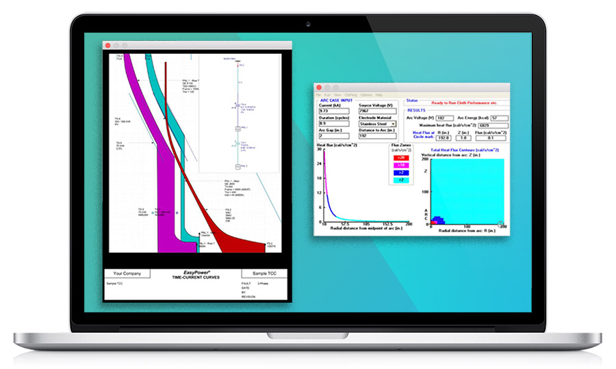
- An engineering study is based on IEEE Guide for Performing Arc-Flash Hazard Calculations (IEEE Std 1584) in most cases and provides the most accurate assessment. The drawback is the expense. Every part of the electrical infrastructure must be collected on-site including transformer data, wire and conduit sizes, types and length; breaker and fuse make, model, rating, settings; panel make, model, ratings; bus duct make, model, rating and length; and any other data related to generators, MCC’s motors, etc. Once collected by an electrician, the data is sent to an engineer who enters it into the software to create the model of the electrical system and perform the analysis of the system. The benefit of doing this level of assessment is the inclusion of short circuit and coordination studies. The short circuit study will determine the available fault current at each device studied. All panels and electrical equipment have a fault current rating and if the level is exceeded, the breakers may not operate and cause an arc flash. The coordination study is important for the reliability of the service and often justifies the cost of the study. As an example, this will determine if a fault in a control panel operates the breaker feeding it or another breaker upstream which may take the entire plant down rather than just at that equipment. This coordination study can also be used to identify changes to protective devices that could reduce the existing arc flash hazard. Other benefits include the development of a one-line diagram of the electrical system and labels stating the arc flash boundary and PPE requirements at the working distance (18” for lower than 600 volts) as well as the shock hazards, approach boundaries and associated PPE requirements.
Categorised in: Arc Flash, Blog, Consultant, Workplace Safety